
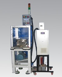
The Armature fling and burst test rig is designed to test the armature along with its commutator for the following tests.
| No. | Name | Description |
|---|---|---|
The details are subject to change and customizable to orders. |
||
| 1 | Proof Testing | The flinging of armatures by free running the test object at pre-settable speeds between 20000 RPM to 50000 RPM for pre-settable time, and by verification by physical dimensional measurements on the test object. |
| 2 | Burst Testing | To evaluate the speed, at which the test object bursts due to the action of centrifugal forces, expected to occur below the maximum test bench speeds upto 50000 RPM. |
1. Load the armature manually
2. Clamp the armature by adjusting the center to center
3. Close the safety door
4. Start the test using start key
5. Motor will run in set speed for set duration
6. Acceleration and Deceleration is settable with the drive
7. Drive will start and stop after the set duration is over
8. The motor is stopped after set time is over
9. Component conditions are monitored manually
| No. | Name | Description |
|---|---|---|
The details are subject to change and customizable to orders. |
||
| 1 | Input | 3 phase 440 V AC 8 KW |
| 2 | Table size | 500W X 750L X 900H mm |
| 3 | Panel size | 600 X 1200 X 300 mm |
| 4 | Operator panel | 400 X 300 X 200 |
| 5 | Maximum speed | 50000 RPM Achieved with in 30 secs |
| 6 | Component clamping | Center to center holding |
| 7 | Length to Hold | 100 mm to 250 mm Adjustable |
| 8 | Maximum weight to hold | 10 Kg |
| 9 | Maximum On time | 5 minutes |
| 10 | No of on Cycles | 5 per hour |
| 11 | Lubrication | Automatic Lubrication system |
| 12 | Loading | Manual |
| 13 | Unloading | Manual |