
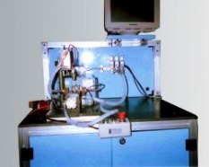
The Starter motor performance test rig is used to test the starter motor in the following methods.
In this test, the motor is switched on with the set voltage. The Magnetic Particle Brake is used to load the motor.
1. The motor is loaded for the minimum load using the powder clutch brake
2. The motor parameters such as voltage, current, torque, speed are measured and displayed, plotted and stored.
3. The load applied to the motor is slightly increased by adjusting the current applied to the powder clutch brake
4. Repeat step 2 & 3 if the motor is not locked. If the motor is locked then the stop adjusting the brake values. Release the load, switch off the power supply to the motor.
5. The graph plotted is the performance curve of the motor, which will display the motor voltage, motor torque, motor speed, input power, output power, efficiency against the motor current.
6. The graph can be printed out using a suitable printer. The data available in the graph is also stored in a separate excel file. The filename can be specified by the user. The graph image can also be stored as JPG format for future reference.
• Initial Voltage setting
• Initial torque setting
• Voltage steps – In steps of 1 volt.
• Torque steps - In steps of 0.1 Nm
• Time duration for each step – 1 to 3 seconds.
1. Load the Motor manually
2. Select the corresponding Program
3. Select the Mode (Normal Mode or Performance curve Mode)
4. Start the sequence using start key
The Test rig indicates the following In Normal Mode
• No load Voltage and Result.
• No load Current and Result.
• No load Speed and Result.
• Load-1 Voltage and Result.
• Load-1 Current and Result.
• Load-1 Speed and Result.
• Load-1 Torque and Result.
• Lock-Torque Voltage and Result.
• Lock -Torque Current and Result.
• Lock -Torque Speed and Result.
• Lock -Torque Torque and Result.
• Load-2 Voltage and Result.
• Load-2 Current and Result.
• Load-2 Speed and Result.
• Load-2 Torque and Result.
Final Result.
| No. | Name | Description |
|---|---|---|
The details are subject to change and customizable to orders. |
||
| 1 | Input Electrical supply |
• Single Phase AC • 230 volts +/- 10 % • current maximum 30 amps |
| 2 | Panel size & Finish | • Length 700 mm • Height 1500 mm • Width 650 mm • Air cooling provided by cooling fan • Powder coated finish |
| 3 | Fixture | • Table height 900 mm • Component loading height 1050 mm • Loading manual • Unloading manual • Clamping Manual |
| 4 | Cycle time |
• Total cycle time for Normal test 17 sec’s • Performance curve test cycle time 25 sec’s Max |